Tracking your hamster
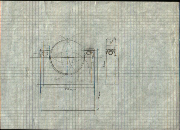
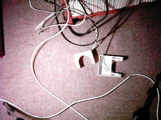
This is the sensor that senses the movement of the hamster in her cage. I use a habitrail cage with tubes in all kinds of sizes. These tubes all have the same diameter, therefore designing an IG-gate for them was fairly straightforward.
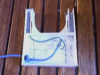
In this picture the LED on the left is the Infrared receiver, the one on the right is the Infrared Transmitter.
|
These are the first designs I've made of the IR-sensor.
|
(Click on any of these images for close up, use back button, to return to this text).
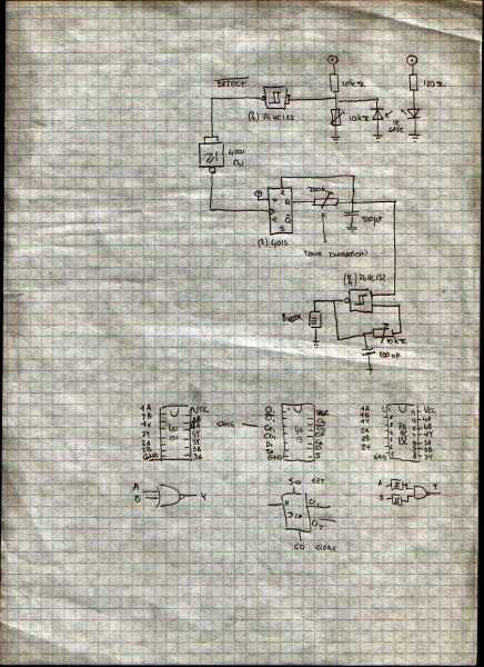
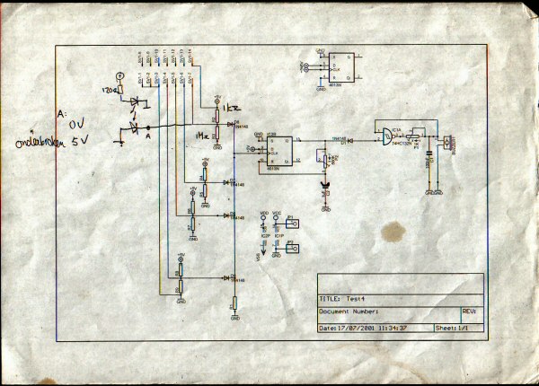
Below right is a schematic I tried to make with an evaluation version of 'Spice' (I think it was called). I thought it would be really cool to design something like this on a computer and let the computer figure out what the best placement of components would be.
Sadly I've never figured out how to do this, with this electronics CAD application. It was a while ago, so maybe the user interface has improved since. But I must admit I never gave it a second try.
|
|
The left schematic above is an IR gate with an oscillator and an output for my computer interface. If the IR-beam gets interrupted, then the IR-detector will suddenly increase it's internal resistance. This will cause a voltage drop on the input of the (inverting) Schmitt-trigger. Because the signal is now inverted by the Schmitt-trigger, an inverter was made of a NOR-gate (of which I have plenty of; see
Design Principle #3). The output of the inverter is the signal that drives the oscillator timer.
Oscillator Timer
This signal is then used as a clock signal on the D-Flip Flop; this will set the output to a logical one. By doing this the capacitor is charged, regulated by the variable resistor. At the time the capacitor reaches the critical logical on voltage level, it will trigger the reset of the Flip Flop. By changing the variable resistor, a change is made in the duration of the produced sound.
Oscillator
The output of the Flip Flop is fed to another Schmitt-trigger, which is used as an oscillator to drive the Piezoelectric buzzer. The Capacitor in combination with a variable resistor determines the audible frequency.
The signal feed that is supplied to the Oscillator Timer must also drive the interrupt lines of the Mppp-i interface (more on that in the near future...) which in its turn signals the computer.
That's all there is to it
This is, how to make a sensor, which also emits an audible beep when triggered. Pretty straightforward and simple isn't it?
Ohhh, I almost forgot to mention that CMOS chips must be used in stead of TTL ones. These different characteristics of CMOS (high input resistance, low power to name just two) are critical in this design. Believe me, I should know, after soldering a test with CMOS which worked, I then build a proper one on construction board. But then I used a TTL equivalent... Needless to say, after many hours I noticed it, it was the CMOS/TTL thing.
I'd love to blame the Chip Manufactures here; why don't they use different colors of plastic for these kinds of differences?...
By the way I've never tested the TTL chip I used, when screwing up. So I can't give you a damage report about this. So please make sure to use CMOS, and put those TTL chips in a different shoeboxes...
|
 More than one
I've made more than one sensor. The interface is currently driven by two of these sensors. Without modifying the interface, I can add another two of these sensors. Too bad I only have the parts (Infrared Emitter and Detector) to make just one more at this time of writing.
|
|
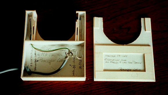
This is a close up of the sensor. I made it in 2000, then it served as a warning device (for me to be notified when) my hamster had woken up.
The front plate on the right, I've lost, when moving to my new home. I know I've seen it somewhere since, but I haven't been able to find it yet.
At least I know I'll find it after I made a new one.
Click on picture of a closeup.
|