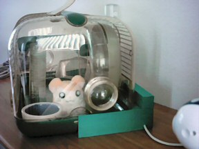
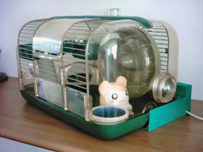
How I automated the Hamster TreadmillThis is the sensor that senses the movement of the hamster-treadmill. It provides an electrical signal to the Mppp-i interface. This signal is recorded and analyzed by the HamsterTracker™ software to provide valuable information. This information must include: The next are derived from the above: (Sorry non-metric users, but; centimeter(s) per second are actually more accurate than inch(es) per second.) |
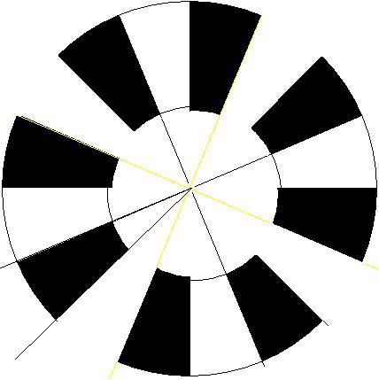
Making of...a treadmill sensorEverything starts with a prototype. On the right is a picture I made with Paint Shop Pro. (You can download a free trial version of this great images editing software on their website.)I know it isn't one of the most pretty images, but once printed (enlarged to a sheet of A4 paper) it is actually quite sufficient. I cut out the figure using scissors and placed it on the treadmill. With a marker I marked the inner and outer edges of the circle. Using a compass I draw neat circles on the design. This gave me quidance for the final cutting of the image. Then I used clear sheets of sticky-bookwrap to stick it to the treadmill. Voila, a test treadmill made in an instant. Please Note: Only do this kind of stuff with your treadmill if you: I don't want to break any Design principle here (#1 and #2)! The picture on the left, is the first prototype of the IR-transmitter and IR-receiver mounted on a piece of cardboard. After fitting the treadmill, I used some CD's to lift the whole cage up, so the treadmill wouldn't drag on the table. While shooting some pictures (as the picture here) I noticed that my little webcam can see infrared light! See the bright blue spot on the treadmill? That's infrared light as seen by a digital camera!!! This observation became a very usefull tool in calibrating all infrared leds. |
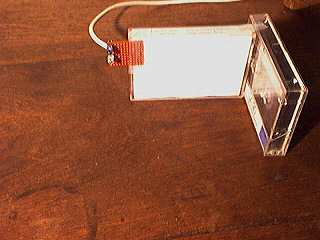 This is Prototype version 2! I've used two tape cassettes, some sticky tape, a lot of patience and the Infrared print (more info on that later). Put it all together, and place it in front of the treadmill. (see next picture).
TIP: Remove (both) tape(s) before putting everything together with cellotape. I couln't listen to 'Curiousity Killed the Cat' & 'King Yellow Man' for over a month! Carefull examination revealed that I got the wrong tape (as mentioned above) in the wrong cassette. And I still glued it shut :-( Luckily it's only cello-tape! |
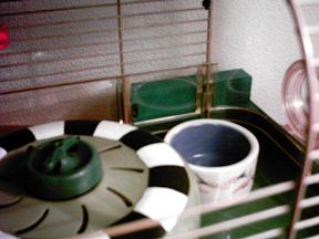
Putting it all together...As soon as I knew that the technique would plausibly work, I've painted a black and white pattern, by using model paint; Gloss White and Matt Black for maximal performance, on the treadmill. To convert the paper barcode to a painted one, I marked all edges of the barcode with the sharp tip of a hobby-knife. On each corner of a black-white and/or white black part, I made a small mark with the knife on the plastic treadmill. I ended up with a 'connect the dots' barcode, once I removed (and thereby, sadly, destroyed) the paper barcode. I used a piece of paper (because of the curvature of the treadmill) and a non waterproof marker to actually connect the dots. This gave a great outline of where to paint, but, as I found out, it's actually a drag. If you whipe it gently, or even just touch it, the non-waterproof-markings vanish instantly! So I ended up drawing it all again, now with a waterproof marker. Advantage of this technique is that it is then pretty hard to mark 'wrong markings' because you should have a general overview of where to mark. (regarding not all of the non-waterproof-markings have misteriously vanished). And therefore not messing up your precious treadmill. Painting was then fairly straightforward. Just a steady hand, patience and a lot of time. The smell of model paint though, brought back pleasant memories of when I was a kid, when I was building (and painting) all kinds of models. |
Theory in practice
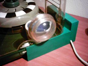
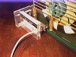
 Here you can see how the sensor can detect movement of the treadmill...
The picture on the left shows how the infrared light is reflected by the white part of the treadmill. The right picture shows that infrared light doesn't (or at least poorly) reflects from a black part. (Look close to spot the difference :-) |
Making of... |
|
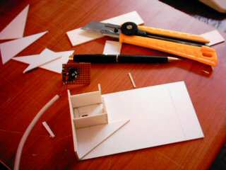
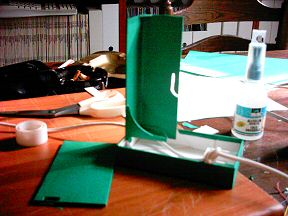
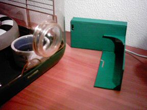
When I started to build the final design of this treadmill sensor, I decided on the 'organic design' approach. In my profession as a (Senior) Software Engineer I'm used to developing by carefull planning. Because this project is hobby project, I opted for this radical design approach. I use photo-cardboard used for framing pictures. This is nice and tough cardboard, although a bit difficult to cut. But with a sharp hobby knife and a straight ruler (I used the back of a saw for this job), you shouln't encounter too many problems. I first cut a so called 'base plate' where I started the design from. Then I carefully cut pieces of board to nicely fit around the small electronic part, which contains the IR-detector and IR-emittor. I Used some other cardboard to fixate all these pieces, just to be sure that it was a bit more sturdy. TIP: Save discarded pieces of board from other projects! As you can see on the picture, these pieces can become very usefull in time (as long as certain angles are straight). |
|
|
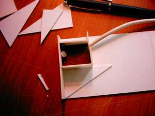
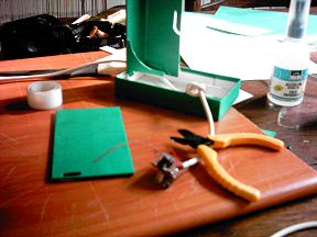
Then I decided that the white color of the cardboard was a bit too obtrusive in combination with my hamster cage, therefore I used some green pieces of paper to furnish it off. This can be a difficult job, dependant on the shape of the sensor. This is a great rainy sunday puzzle! I then had to disconnect the wires to my circuitboard, carefully taking notes where all the wires should hook up. I then slipped the wire (a standard network cable, because I needed three wires, and I couldn't find anything else in my shoebox on the attic), through the hole I made in the cardboard casing. If you make a simple knot in this wire, after it's been put through the hole, then you can't pull it out of this sensor. (Without completely destroying the sensor, that is). Some time later, I wanted to connect all wires again, seemed that I've lost my notes where each wire should connect to. :-(( So I was forced to figure it out all again. Luckily I made some notes on the circuitboard with a waterproof marker (you really need a waterproof marker in this project!). But still it took me a bit longer than expected. |
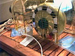
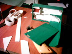 This picture clearly shows another design principle. I needed to be able to get to (a lot of 2's here) the inside of this sensor at any time.
Just in case I needed to make a modification, look or yell at it. This is what my sensor looks like, when opened. I use this picture a lot, because I hope I never have the need to open it up again. Needless to say, I've found the notes I made after I got it all hooked up and functioning. |
Posing like a Playboy model...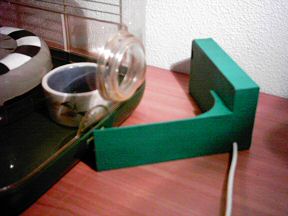
|
|
|
|
Sigh... Admire all these positions!
|
|
|
© Copyright 1994 - 2008, Peacoque Labs
ing. Mathijs A. van der Paauw